During a VHF Rover trip while trying to contact N0LD on 23 cm we encountered a lot of frustration. Phone seemed out of range so Randy, N0LD, and I began trying to use the WSJT-X mode Q65. He eventually realized the 1296 Mhz frequency was drifting around. Decodes were sometimes working but mostly failing. He observed my signals on his frequency spectrum waterfall plot several hundred hertz away from where I thought I was transmitting! This is a problem for Q65 which requires greater frequency stability and other hints like where to expect a signal in the first place. We observed as the IC-9700 goes through it’s transmit and receive cycles and warms up/cools down the clock drifts with the temp. To further aggravate the situation when the heatsink fan turns on the clock quickly drifts the other way while it’s transmitting as the fan removes heat from the oscillator circuit!
Randy did some research and learned about a highly precise local oscillator with GPS disciplining (feedback) for the IC-9700. This kit from Leo Bodnar has a frequency stability that approaches 1×10-12 or 0.000001 ppm. That’s incredibly stable! On the ICOM IC-9700 brochure they list the frequency stability as “Less than ± 0.5 ppm (–10°C to +60°C; 14°F to 140°F)”. That’s not great for a radio that operates at 1296 MHz or even 440MHz. This is basically the same stability for the IC-7610 where the maximum frequency is only 50MHz.
It never occurred to me to consider my brand new radio to have a low cost, unfit, local oscillator. I assumed the IC-9700 would have a more precise clock for it’s bands however it is a bit of an old radio and they likely didn’t want to build a few thousand units with each costing an additional theoretical $20 for a TCXO (Temperature Compensated Crystal Oscillator) or even $100 for a OCXO (Oven Controlled Crystal Oscillator). Also it was for the Amateur market, not commercial radio and manufacturers are always concerned a new product line will not sell well. The forever battle between Engineers and Management!
The Leo Bodnar Electronics “High Stability Kit for ICOM-9700” is 3 pieces. It has the (single or dual output) highly stable frequency generator, an injection board to mount inside the radio and an SMA connected GPS antenna ‘magnetic puck’. The Reference Injection board basically sits on top of the Phase Lock Loop (PLL) of the Local Oscillator and presents a stronger signal than the original ICOM Local Oscillator thus causing the PLL to lock onto the new signal for the Local Oscillator. It works great and it’s brilliantly simple!
I purchased the dual output LBE-1421 so I could dedicate one output to the IC-9700 and use the other independant output for a 10 MHz reference to the IC-7610 or for testing with other things. Output 1 of the dual unit can operate from 1 Hz to 800 MHz and output 2 can operate from 1 Hz to 1.4 GHz!
Before alerting or connecting the Bodnar Reference Injection kit I used output 2 as a frequency generator sending it’s signal into an open ended piece of coax. I placed this piece of coax over the IC-9700. Doing this I could see the IC-9700 local oscillator was off by about 250 Hz on 70cm (harmless for repeater or satellite use). This test was in a stable temperature room with receive only. During the VHF Rover contest however I was in the car during June and sometimes the radio was shaded, sometimes it was not. This certainly explains why Randy could observe my frequency drift and why we had troubles!
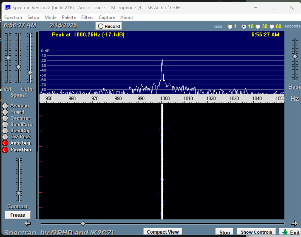
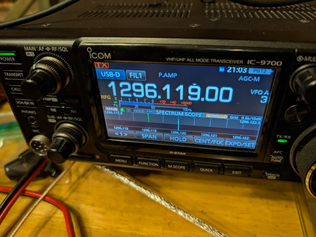
I also set the Bodnar frequency generator to output a frequency at 1,296.12 MHz and I set the ICOM to 1296.119 MHz USB. This also produce a tone 1 KHz down that was easy to observe on the frequency spectrum waterfall plot. As expected the ICOM local oscillator was off causing the tone to be off however I failed to write-down the error before I began removing screws from the radio.
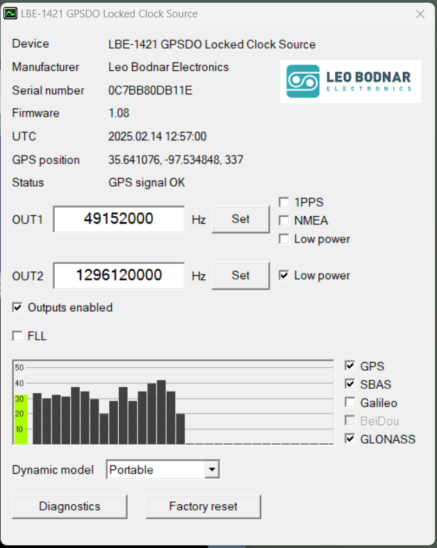
I downloaded the software from Leo Bodner’s site to configure my device, LBE-1421, and I downloaded the latest firmware. Fortunately the Configure software is just an EXE that I could run – no install required. I updated the firmware and then set about observing how far off the IC-9700 L.O. was.
- In the Configuration utility change Output 2 to 1296120000 and click SET.
- Click “Outputs enabled”
- Connect a piece of open ended coax to Output 2 and lay it across the IC-9700 so it will pick-up the signal.
I used Spectran software for the frequency spectrum waterfall plot. Spectran is free and available here. I could have also used WSJT-X’s spectrum scope but Spectran was easy to use since it would not try and control the radio.
All I had to do was adjust the IC-9700 reference settings to move the tone from 1250 Hz to 1kHz.
- Tune the IC-9700 to 1296.119.00 USB and look for a tone on the spectrum display plot somewhere near 1khz.
- Spectran displayed where the Peak Signal frequency is located which is handy.
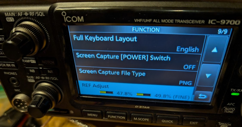
- On the ICOM go to SET | Function then to page 9 of 9 | REF Adjust
- I adjust the local oscillator reference freq until I had the audio tone at 1kHz.
After this setup I then set Output 1 to the ICOM’s LO freq of 49152000.
I unchecked “Low power” and clicked “Set”.
After attaching the Output 1 to the injection board and turning the radio on again I confirmed the tone was where it should have been.
Once I was completely done I set output 2 back to 10000000 and set power output back to LOW. I will use output 2 as a reference input to my IC7610 when rovering.
In my Rover I have a 12v USB charger that powers 6 devices off my LiFePO4 pack because I have a tablet, S.A.T. to control the rotor, my phone, and now the LBE and all of this needs the power to be uninterrupted.
Here I could see the software for configuring the Leo Bodnar LBE-1421. I used Output 2 as my signal generator while testing and used Output 1 as the local oscillator for the IC-9700.
Once I have the IC-9700 properly adjusted the tone is at 1000 Hz on the IC-9700 spectrum scope as well.
My adjustments to the IC9700 LO.
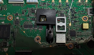
Regarding placement of the signal injector – I removed the foam cover on the IC9700’s oscillator, cut a hole in it very carefully for the Bodnar signal inductor to fit through and then put it all back together. I would hope this would prevent the LO from drifting drastically if I’m using the radio without the Bodnar powered on.
Side view of the signal injector board as mounted.

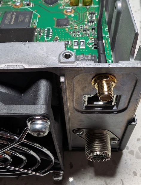
And the SMA connector from inside the chassis:

And outside the chassis
I would say the hardest part was looking around in the garage when it was 23 deg F for the right size wrench and socket, and paying for the components. With them however I should now be able to make Q65 contacts on 1296, 440 and 144 MHz. Therefore I’ve certainly added value to the radio, not just worthless bling.