Again, I wasn’t expecting great numbers and fully expected I would need a remote tuner to use this in the attic. I was wrong! From my experience with the variety of dipoles I’ve built in the attic I’ve known that the aluminum coated air duct doesn’t really cause problems nor do the lightning rods, as long as they are not within the near electric field and contributing to capacitance. A few inches is good enough for 100 watts. Why did I do it? I enjoy doing testing different antennas and learning about them and I’m really, really intrieged by having a gain antenna made with wire and fiberglass rod as opposed to huge amounts of aluminum in the sky. It’s exciting to me – and that I have all this hidden in the attic!
Other observations: Years ago I went around replacing the GFCI outlets that tripped anytime I transmitted. I didn’t replace them all, just the ones having problems. The new antenna has added one more to that list. The other issue is the kitchen oven – when i’m transmitting evidently it’s clock stops counting ticks and it falls behind! After half a day or more on the radio the oven clock may be off by 1/2 hour or more. So, if the wife is baking something over a long period of time I maybe should use a different antenna.
Keep in mind, the base of the antenna is 17 foot above ground, well, above the concrete floating slab, then a foot of sand, and then the clay soil this house sits on. So it’s only about 1/2 the proper minimum height. The good news however is that 20m is on top of the inverted umbrella so it is about 22 ft high. One would expect the SWR to not be great – but you would also expect the radiation pattern to look more like a vertical dipole than a pattern indicating directivity. I can report from monitoring my pattern on PSKReporter that it looks better than I expected. It does have a front and back pattern. Is it better than the inverted V at this height? I can’t answer that since I can’t do a side by side and the solar environment has drastically changed here on the starting edge of Solar Cycle 25.
Ok, here are the screen grabs for each band. (I would have loved to have one of these RigExpert analyzers in college! So amazing! We had to calculate these on HP-48SX calculators and plot on paper {yes I know, people before me did it with a slide rule}).
For coax I am using Wireman Super 8 low loss (like LMR400 flex).
At the other end is a DX Engineering DXE-HEXX-BAL-KIT, 1:1 Balun and then the antenna.
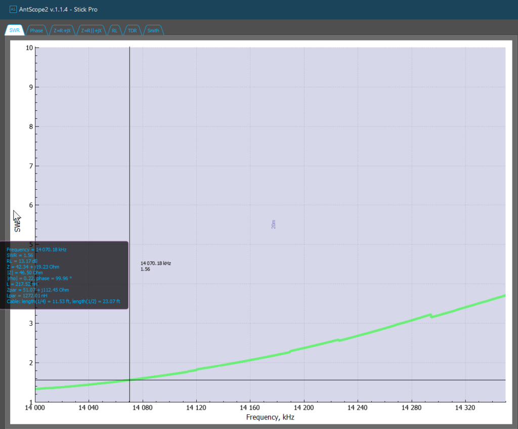
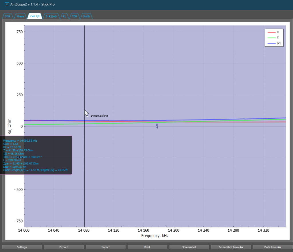
20m plots
Everyone’s favorite, the SWR plot. Looks like on 20 I can use it for CW and data but phone will need a remote tuner.
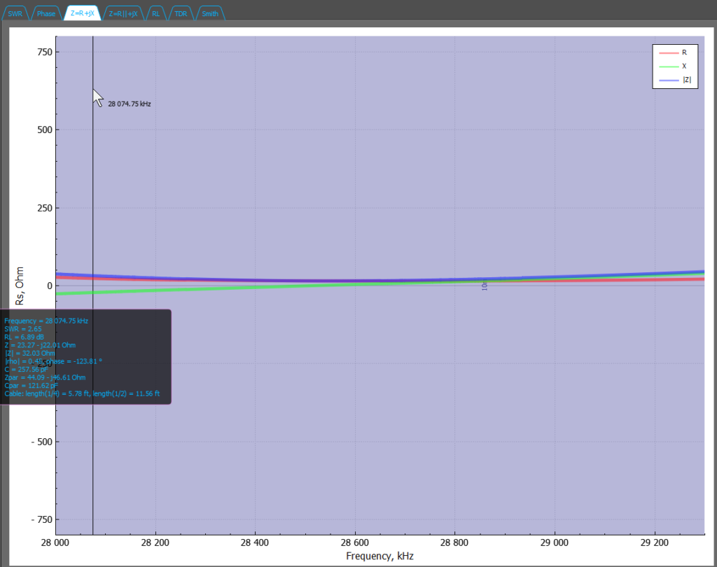
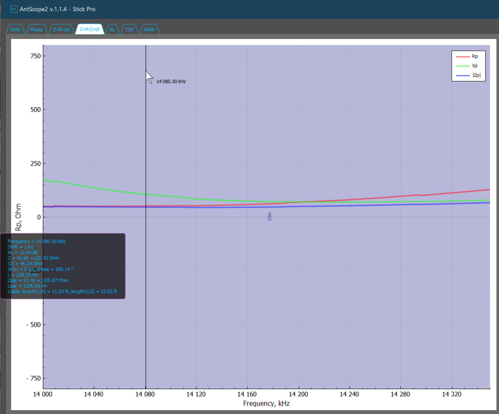
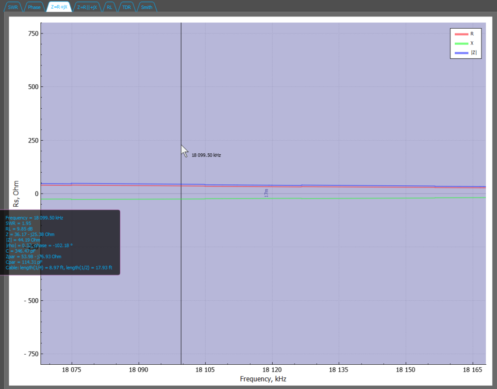
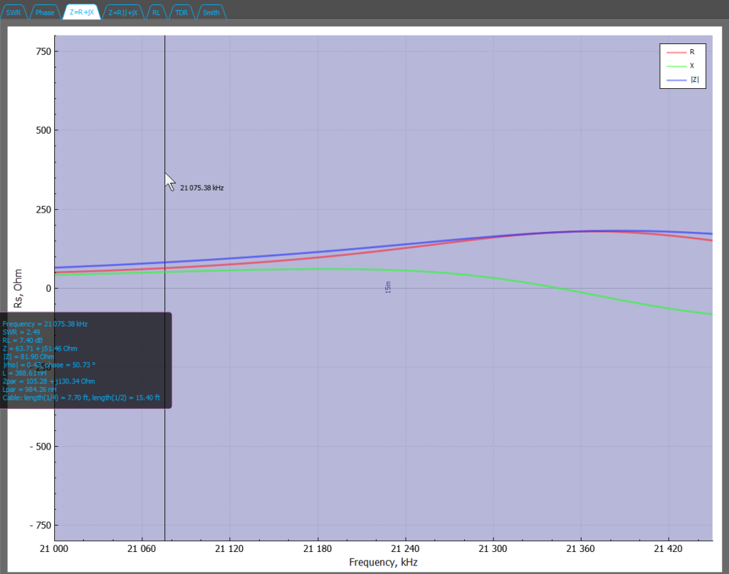
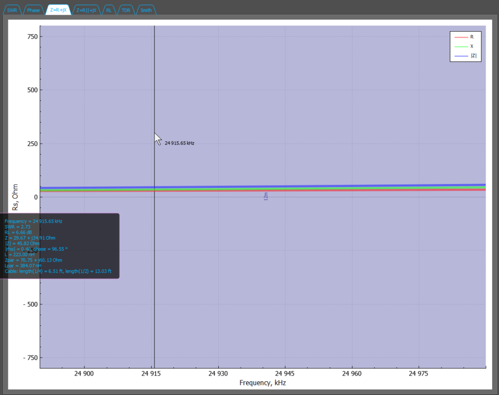
Z=R+jX – shows a plot of R, X, Z (series model)
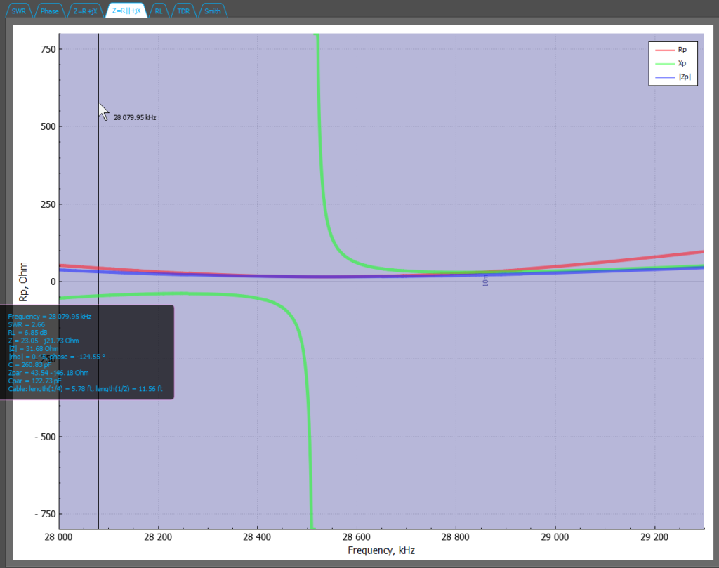
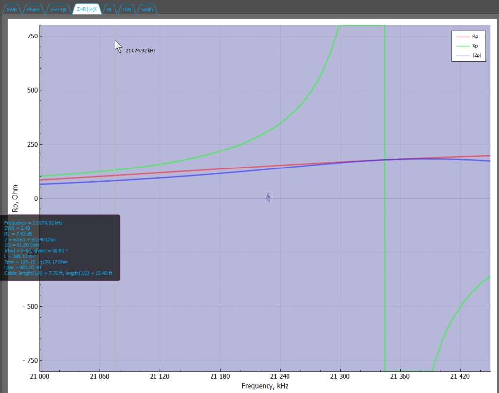
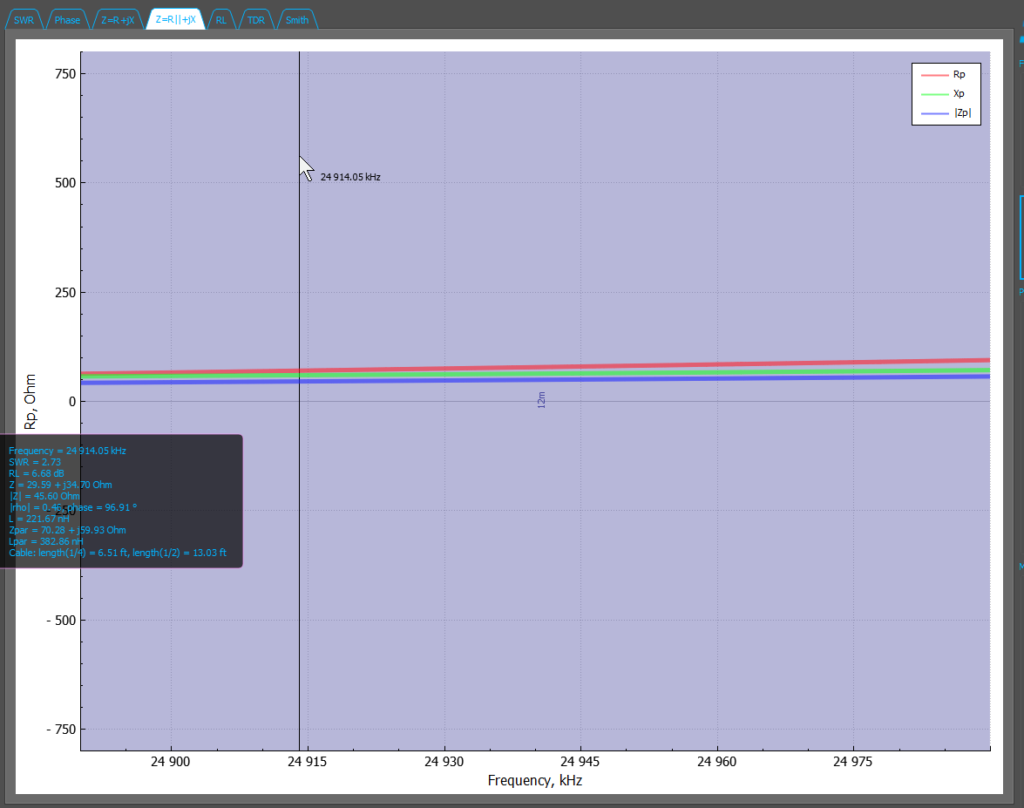
Z=R||+jX – show a plot of R, X, Z (parallel model). I’m including these but I’m thinking this is here because the ‘Antenna Analyzer’ is really a transmission line analyzer and it’s just analyzing what it sees on the transmission line knowing that something is on the end (and it has no idea if it’s a series or parallel circuit). With an antenna on the end and nothing between, we are a series circuit (ok, there is an 1:1 impedance transformer to ensure the current in both sides is the same).
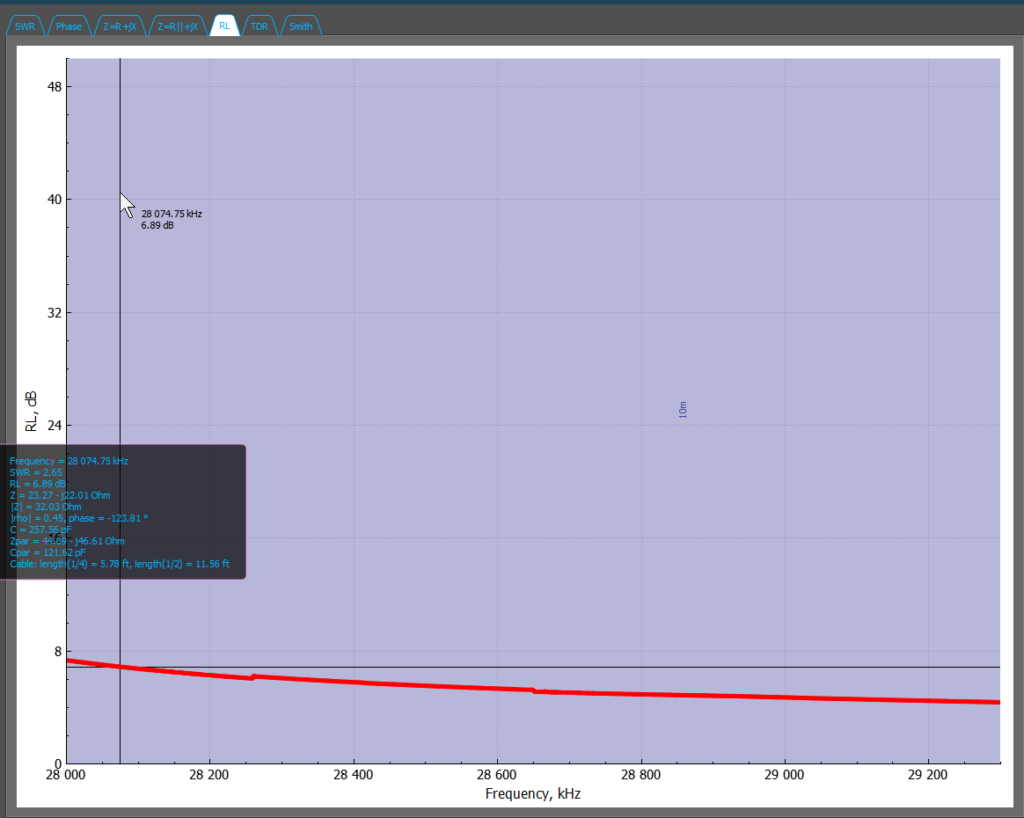
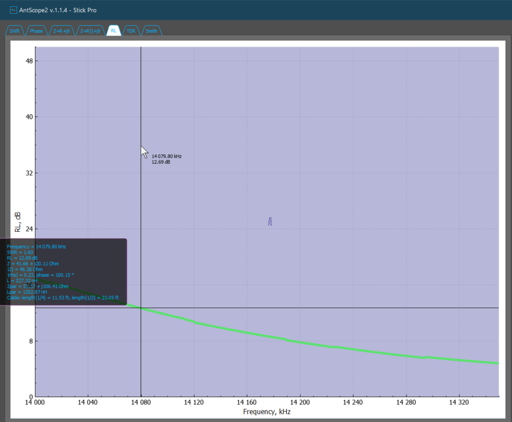
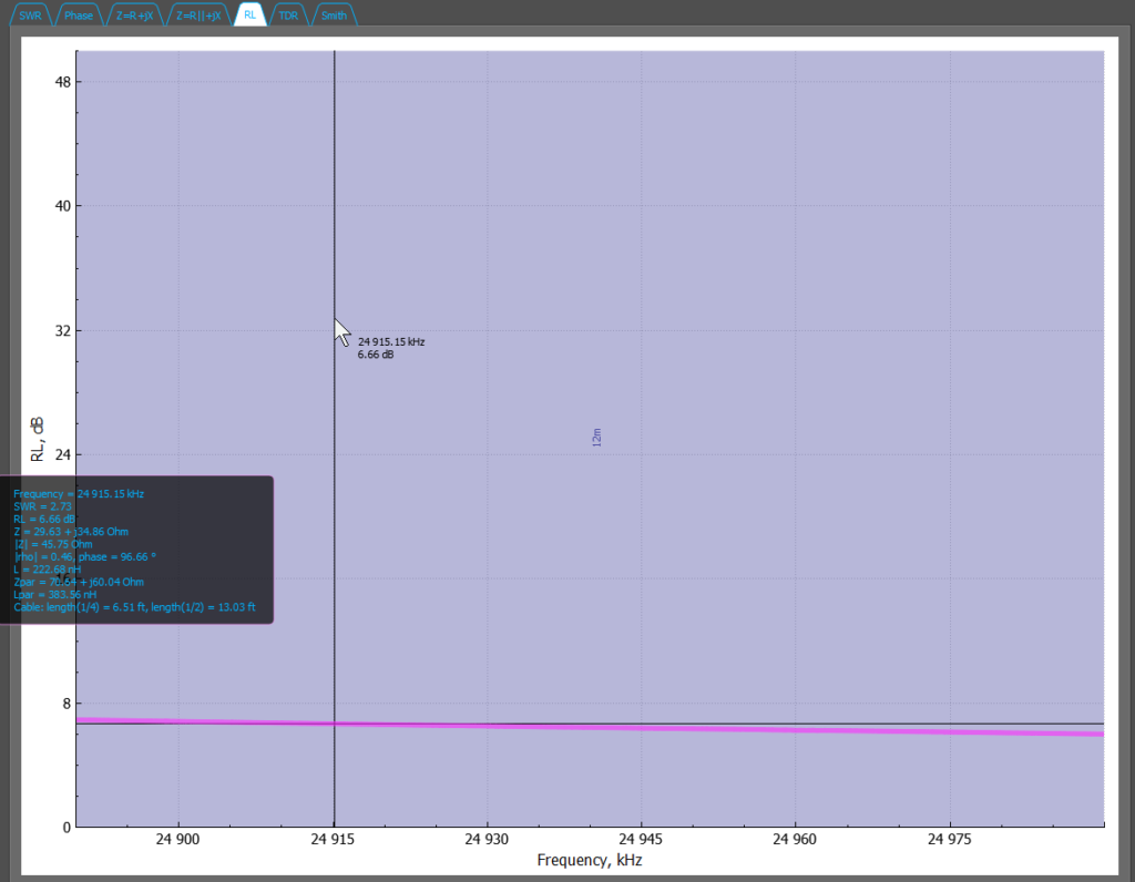
RL (Return Loss) is the db loss plotted due to load mismatch.
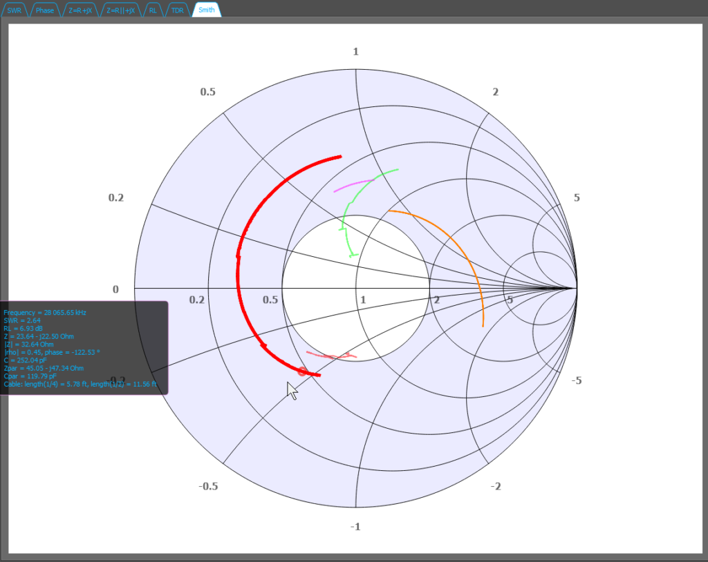
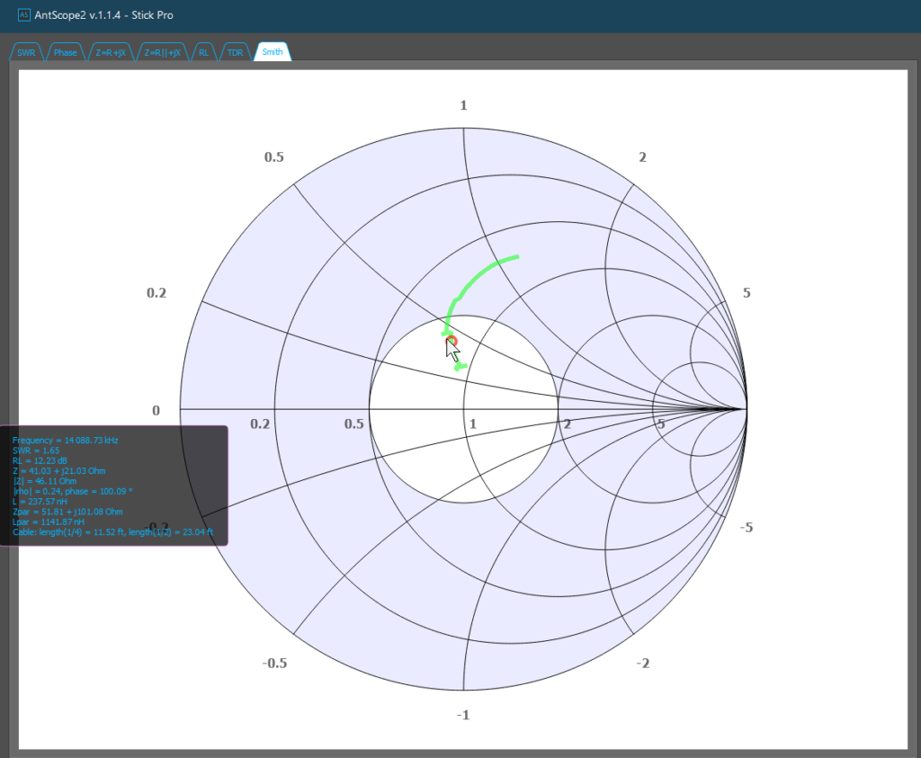
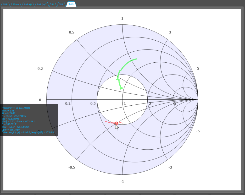
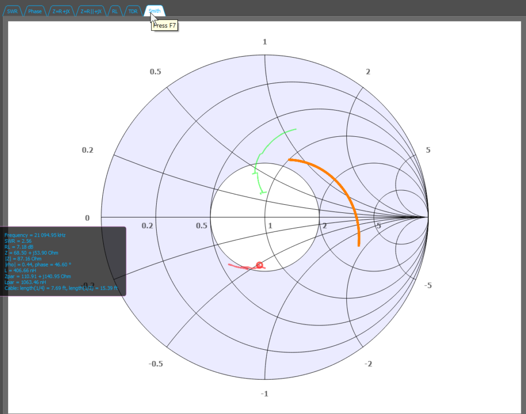
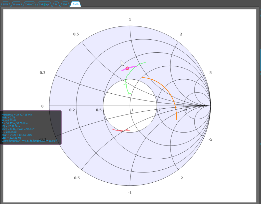
The Smith chart!
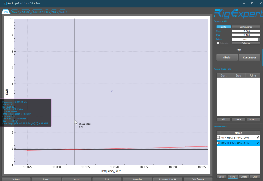
17m plots
The SWR plot. Looks like on 17 I can use it for CW/data/phone, no tuner.
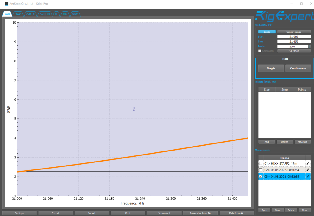
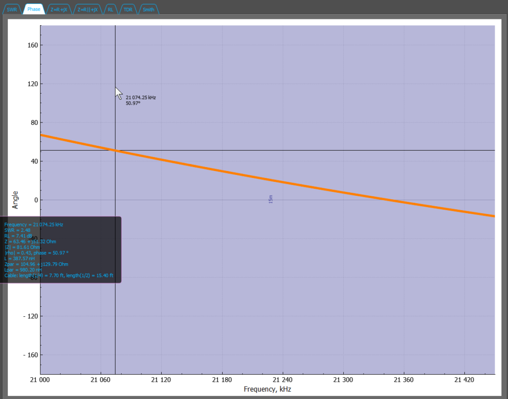
15m plots
Looks like on 15 I can use it for CW and data but phone will need a remote tuner.
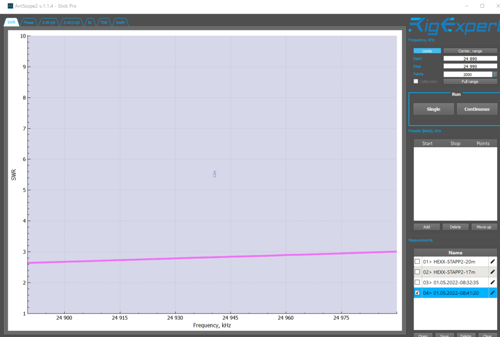
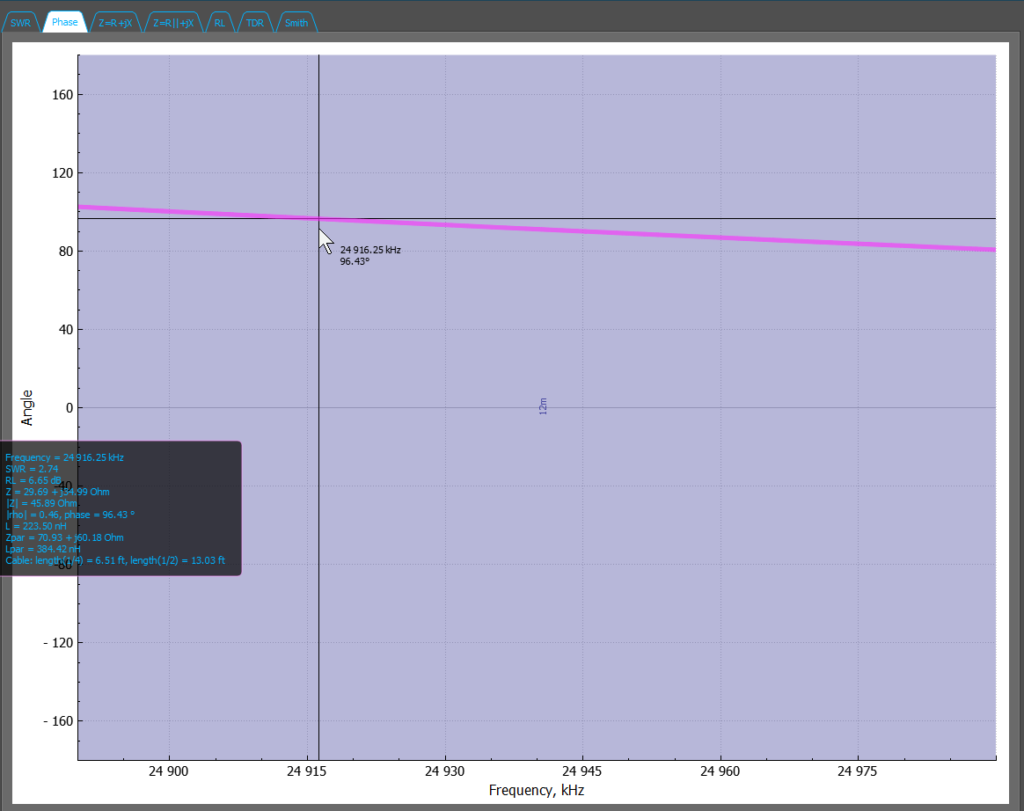
12m plots
Looks like on 12 I can use it for CW/data/phone.
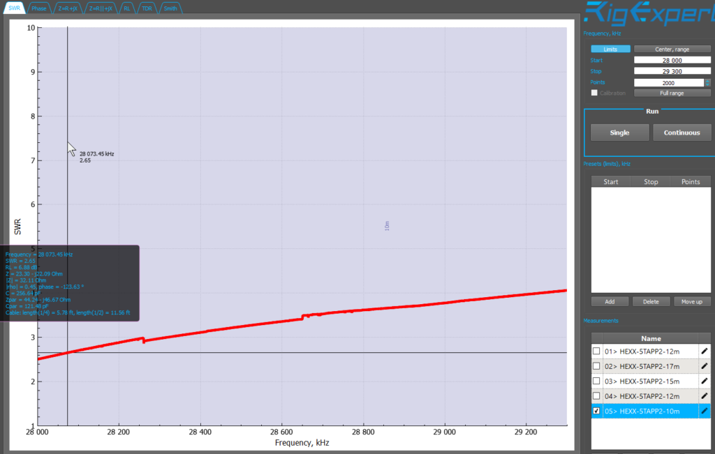
Band 5, 10m plots
Again on 10 I can use it for CW and data but phone (like 28.390 net) will need a remote tuner.